
Using PC Fan (12V) for 10-Inch Rackmount Setup
I recently put into use a 10-inch rack mount for self-hosting/home lab. Here’s how I am running the cooling fan now.
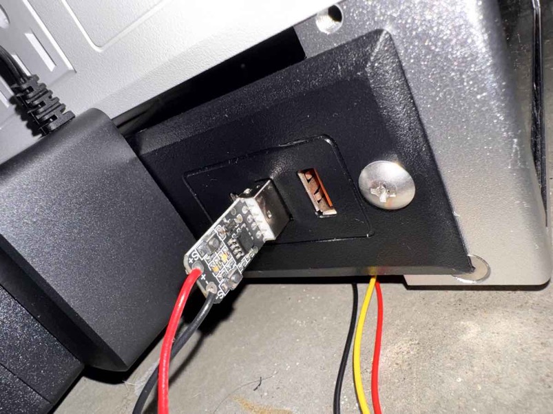
The wires running to the fan cooling the rackmount can be spotted below the USB power supply.
10-inch rackmount setup
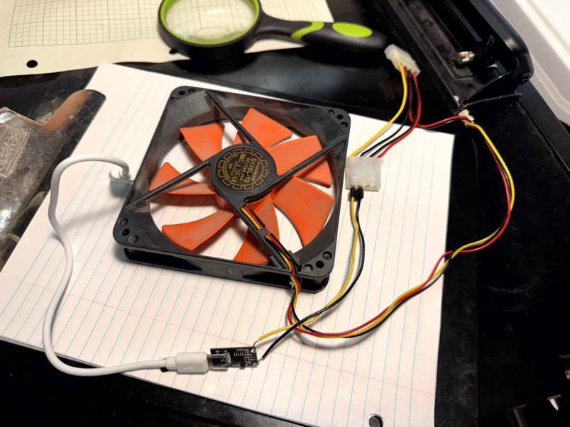
The DeskPi RackMate T1 Rackmount comes with an optional bottom fan-mount that accepts 2 X 80 mm or 1 X 120 mm fans for blowing air around aka cooling. I have spare 120 mm PC cooling fans so I attached one of those when I built it. The spare PC fans run off 12V and have a 3-pin PC motherboard fan connector as well as 4-pin Molex connectors.
When I installed originally, I was using a 12V feeder that came off a Raspberry Pi Power-over-Ethernet (PoE) HAT that was running in the rack. This served perfectly fine even running through the PoE connection if the OS on the Raspberry Pi was shutdown.
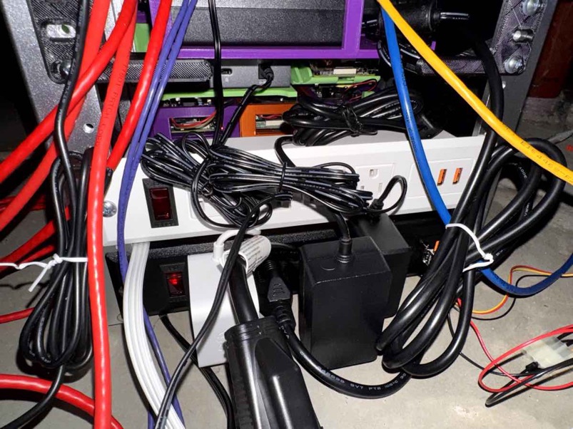
In the photo there is a white plastic and a black plastic power strip that each have 1 USB-C and 2 USB-A power output ports. You can spot the “orange” USB ports which some use to signify power-only ports.
Powering the Cooling Fan from USB
Why change? Eliminating the particular PoE HAT/Pi dependency, as well as installing an improvised Power Distribution Unit (“PDU”) were reasons. I found some 10-inch power strips that mount exactly into a 10-inch server mini-rack. Additionally these have USB-C PD and USB-A QC sockets, which can output 9V and 12V as well as the standard USB 5V.
To access the 12V for the PC fan, a “trigger” device is employed that tells the USB port to output 12V. These devices are widely available and can support USB-PD, QC, and USB-A or USB-C. I had some in stock so let’s use them.
Creating a USB-Powered PC Fan Supply
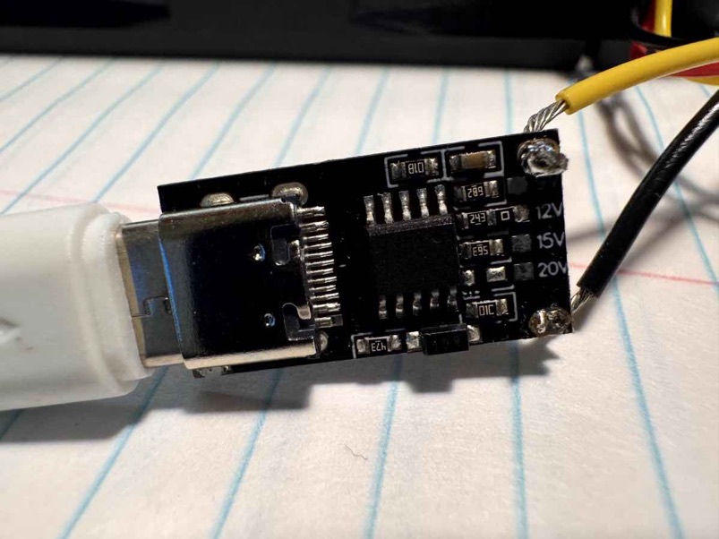
Have 22 AWG stranded hook-up wire. Soldered into the positive and negative outputs of the USB-C input trigger PCB.
In the photo, the output holes were drilled for 24 AWG diameter wire, but I was able to make the wider stranded 22 AWG wire work. You can also see the (factory-set) solder jumper - a zero-ohm resistor - on the board setting the 12V but 9V, 15V, and 20V also available.
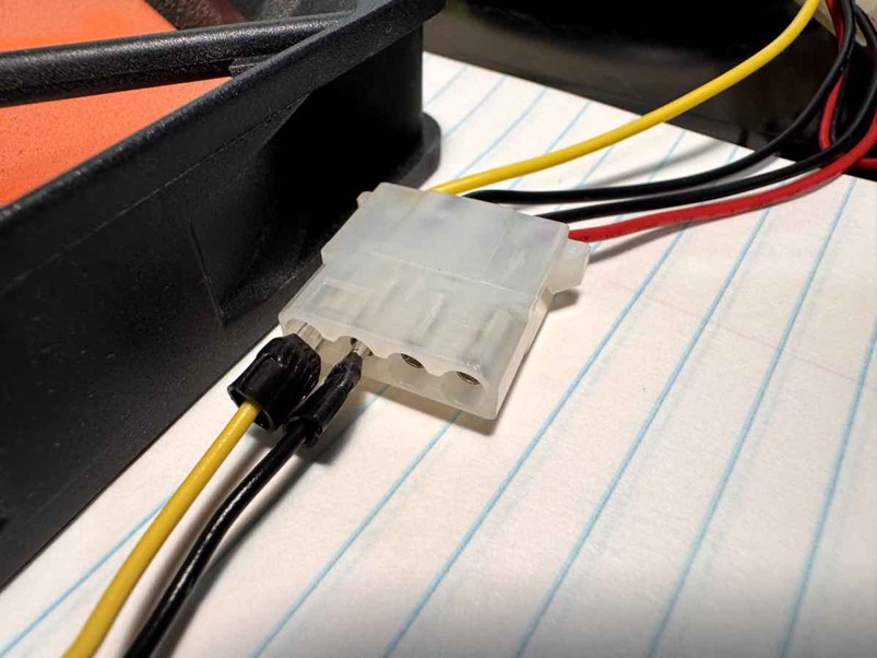
I have some tubular connector crimp terminals that happen to closely match the diameter of the female Molex connector, and so put these on the other end of the 22AWG hookup wires. Just a friction fit – no soldering on this end.
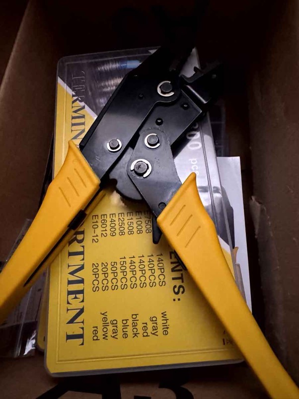
Crimp tool was used, but I found that crushing the shroud and metal tube on the tubular bullet connector with a pliers held the wire in place better.
It turns out that the USB-C trigger converter– while labeled for USB-PD– also worked fine with the USB-A QC USB power supplies.